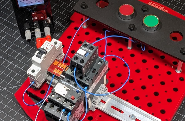
High-Voltage Motor Wiring Diagram: Understanding and Implementation

Introduction to High-Voltage Motor Wiring Diagrams
A high-voltage motor wiring diagram is an essential reference for engineers, electricians, and maintenance personnel who work with industrial motors. It visually represents the electrical connections, components, and pathways within a high-voltage motor system. Proper understanding of wiring diagrams is crucial for safe installation, troubleshooting, and maintenance of high-voltage motors.
In industrial applications such as power plants, manufacturing facilities, and heavy machinery, high-voltage motors are commonly used for driving large loads. Accurate wiring diagrams ensure that these systems operate efficiently and safely.
Importance of High-Voltage Motor Wiring Diagrams
High-voltage motor wiring diagrams serve several vital purposes in industrial settings:
- Guidance for Installation: Ensures correct electrical connections and configuration during motor setup.
- Troubleshooting Tool: Helps identify faults, short circuits, and wiring errors quickly.
- Maintenance Reference: Assists technicians in replacing components or modifying circuits safely.
- Compliance: Ensures adherence to electrical standards and safety regulations.
Without a proper wiring diagram, the risk of incorrect connections, equipment damage, or electrical hazards increases significantly.
Components Shown in a High-Voltage Motor Wiring Diagram
A typical high-voltage motor wiring diagram includes multiple components that illustrate how electrical power is distributed within the motor system. Key components include:
- Stator Windings: Represent the stationary part of the motor where electrical energy is converted into magnetic flux.
- Rotor Connections: Show how the rotating part of the motor interacts with the stator.
- Power Supply Lines: Include high-voltage input connections such as three-phase lines.
- Circuit Breakers and Fuses: Safety devices to protect the motor from overload or short circuits.
- Contactor and Starter Connections: Illustrate how the motor is started and controlled.
- Grounding Points: Ensure the motor is safely grounded to prevent electrical hazards.
These elements provide a comprehensive view of the motor’s electrical design, making installation and maintenance easier and safer.
Types of High-Voltage Motor Wiring Diagrams
High-voltage motor wiring diagrams can vary based on motor design, application, and control method. Common types include:
Single-Line Diagrams
A simplified representation showing the main power flow, major components, and connections without detailed wiring paths. Single-line diagrams are useful for general overview and system planning.
Detailed Wiring Diagrams
Provide a complete depiction of all electrical connections, including internal motor connections, terminals, and control circuits. Detailed diagrams are essential for installation and troubleshooting tasks.
Schematic Diagrams
Emphasize functional relationships between components rather than physical connections. They are useful for understanding control logic, relays, and protection circuits.
Terminal Diagrams
Show specific terminal points of a motor, including voltage levels and winding configurations. Terminal diagrams are particularly helpful during motor testing and commissioning.
See also: The Role of 5-Axis CNC Machining in Modern Manufacturing
Understanding High-Voltage Motor Wiring Configurations
High-voltage motors can be connected in different configurations depending on voltage levels and system requirements:
- Delta Configuration: Connects each winding in a triangular loop, suitable for higher current applications.
- Star Configuration: Connects windings in a Y-shape, commonly used for starting motors at reduced voltage.
- Parallel Connections: Used in multi-motor systems for balancing load and ensuring uniform operation.
Proper selection of configuration is critical for motor efficiency, starting characteristics, and overall system safety.
Safety Considerations
Working with high-voltage motors requires strict adherence to safety protocols. Wiring diagrams play a crucial role in preventing accidents and equipment damage. Key safety measures include:
- De-energizing Circuits: Always ensure power is disconnected before working on a motor.
- Proper Grounding: Verify grounding connections as indicated in the diagram.
- Use of Protective Equipment: Wear insulated gloves, goggles, and follow lockout/tagout procedures.
- Voltage Verification: Measure voltage at terminals before initiating any maintenance.
- Following Manufacturer Guidelines: Adhere to motor-specific instructions in the wiring diagram.
Understanding and following these safety measures can prevent electrical shocks, fire hazards, and damage to the motor system.
Common Issues Identified Through Wiring Diagrams
High-voltage motor wiring diagrams help identify and troubleshoot various issues efficiently, such as:
- Phase Imbalance: Incorrect wiring may lead to uneven voltage distribution across motor windings.
- Overheating: Faulty connections or short circuits can cause excessive heat in the motor.
- Motor Failure: Incorrect starter connections or control circuits may prevent the motor from operating.
- Ground Faults: Missing or improper grounding can pose severe safety risks.
By using the wiring diagram as a reference, technicians can isolate the problem and implement corrective measures accurately.
Modern Tools for Wiring Diagram Interpretation
With advancements in technology, digital tools have become essential for reading and interpreting high-voltage motor wiring diagrams:
- CAD Software: Allows engineers to design and modify wiring diagrams digitally for better accuracy.
- Simulation Tools: Enable testing of motor connections and control logic before physical installation.
- Mobile Apps: Provide on-site access to wiring diagrams for maintenance personnel.
- Interactive Diagrams: Some manufacturers provide interactive diagrams to highlight connections and safety points.
These tools improve efficiency, reduce errors, and support training for new technicians.
Conclusion
A high-voltage motor wiring diagram is a critical resource for the installation, operation, and maintenance of industrial motors. It provides a clear understanding of electrical connections, safety requirements, and control mechanisms. By correctly interpreting these diagrams, industries can ensure safe, reliable, and efficient operation of high-voltage motors in various applications.
Regular reference to wiring diagrams during troubleshooting and maintenance enhances operational longevity and minimizes downtime. In addition, adherence to safety standards and proper configuration based on the diagram ensures both personnel safety and equipment reliability.
A high-voltage motor wiring diagram is more than just a technical illustration; it is a roadmap for ensuring that complex motor systems function efficiently and safely in industrial environments.


